MIM
What Is MIM?
Process Overview
When to Use MIM
General Guidelines
Technology Comparisons
Materials Range
Materials List
Design Guidelines
Designing for Manufacturability
Uniform Wall Thickness
Thickness Transition
Coring Holes
Draft
Ribs and Webs
Fillets and Radii
Threads
Holes and Slots
Undercuts
Gating
Parting Lines
Decorative Features
Sintering Support
Secondary Operations

Gating
Feedstock enters the mold cavity through an opening called a “gate”; due to the high metals loading of MIM feedstock, these openings are generally much larger for MIM than for plastic injection molding. Because gates usually leave a mark on the finished part where they are separated from the molded form, locating them involves balancing the demands of manufacturability, function, dimensional control, and esthetics.
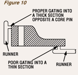
As shown in Figure 10, gates are generally best located on the parting line of the mold, positioned so the flow path impinges on a cavity wall or a core pin. Additionally, for a component with different wall thicknesses, it is usually placed at the thickest cross section so the material flows from thick to thin section. Such a placement eliminates voids, sink marks, stress concentrations, and flow lines on the part surface. If the part will be produced in multiple cavities, added consideration must be given to gate size and placement to assure that an identical amount is delivered to each cavity at a balanced fill rate.

