MIM
What Is MIM?
Process Overview
When to Use MIM
General Guidelines
Technology Comparisons
Materials Range
Materials List
Design Guidelines
Designing for Manufacturability
Uniform Wall Thickness
Thickness Transition
Coring Holes
Draft
Ribs and Webs
Fillets and Radii
Threads
Holes and Slots
Undercuts
Gating
Parting Lines
Decorative Features
Sintering Support
Secondary Operations

Undercuts
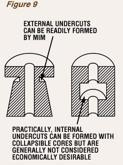
External undercuts as shown in Figure 9 can be readily formed on a parting line using a split mold; where additional mold members are required to produce them, tool costs are increased and production rates decrease. Some internal undercuts can be produced using slides while some others may be molded through the use of collapsible cores. The added costs and potential flashing problems that may ensue in these cases dictate avoidance of internal undercuts in most MIM designs.
Internally connected holes are possible, as shown in Figure 8b. To prevent potential sealing-off problems and issues with flashing, careful consideration must be given to the design. If possible, one hole should be D-shaped in order to provide a flat on the core pin for a robust tool seal-off, as well as to eliminate inordinate wear of the feathered edges that would otherwise be required on the contoured face of the mating member.

