MIM
What Is MIM?
Process Overview
When to Use MIM
General Guidelines
Technology Comparisons
Materials Range
Materials List
Design Guidelines
Designing for Manufacturability
Uniform Wall Thickness
Thickness Transition
Coring Holes
Draft
Ribs and Webs
Fillets and Radii
Threads
Holes and Slots
Undercuts
Gating
Parting Lines
Decorative Features
Sintering Support
Secondary Operations

Parting Lines
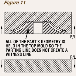
The parting line is the plane in which the two halves of the mold meet. To the extent possible, all features should be oriented perpendicular to the parting line to facilitate removal from the mold. Normally, the parting line is transferred to the surface of the part as a witness line, an unavoidable result of two mating mold members. In some cases, as in the example shown in Figure 11, the full part geometry can be maintained in the upper half of the mold, in which case the parting line would be along the bottom edge of the component and no witness line would be created. At other times, the mold may be designed to separate along an inconspicuous edge, thus “hiding” the parting line.
A parting line that can be contained in a single plane is preferred. However, it is sometimes necessary to modify the simple shape in order to mold desirable features. The added complexity, although it increases the cost of fabricating and maintaining the tools, may be cost effective when the features it molds would otherwise require machining or assembly operations.

