MIM
What Is MIM?
Process Overview
When to Use MIM
General Guidelines
Technology Comparisons
Materials Range
Materials List
Design Guidelines
Designing for Manufacturability
Uniform Wall Thickness
Thickness Transition
Coring Holes
Draft
Ribs and Webs
Fillets and Radii
Threads
Holes and Slots
Undercuts
Gating
Parting Lines
Decorative Features
Sintering Support
Secondary Operations

Threads
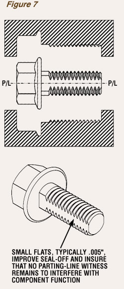
Both internal and external threads can be formed by MIM; however, tapping internal threads is usually more precise and cost effective than using unscrewing cores. The optimum location for external threads is on a parting line of mold members to eliminate the need for unscrewing the mold members that form them. To hold a thread tolerance on a thread diameter, narrow flats—typically .005”—at the parting line are generally specified, as shown in Figure 7. This insures proper mold seal-off, reduces the likelihood of a parting-line vestige, and eliminates problems with flash in the root of the threads, thus reducing mold maintenance.

