MIM
What Is MIM?
Process Overview
When to Use MIM
General Guidelines
Technology Comparisons
Materials Range
Materials List
Design Guidelines
Designing for Manufacturability
Uniform Wall Thickness
Thickness Transition
Coring Holes
Draft
Ribs and Webs
Fillets and Radii
Threads
Holes and Slots
Undercuts
Gating
Parting Lines
Decorative Features
Sintering Support
Secondary Operations

Sintering Support
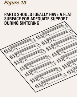
During the debinding and high-temperature sintering processes, green parts shrink about 20%. At this time, the parts must be adequately supported to minimize the possibility for distortion. As metal injection molded parts are typically placed on flat ceramic plates or trays, as shown in Figure 13, it is ideal that they be designed with a large flat surface, or several component features that have a common plane, so that standard fixtures can be used. Parts that have long spans, cantilevers, or delicate points may need to be supported with part-specific fixtures or setters, which can be expensive to produce.

